Definition of Length
Single Mode green Laser
Two Beam Interference
Homodyne Interferometer
Fringe Detection and Counting
Quarter and half wave plate
Interpolation of Interference Fringes
Computer controlled stepper motor
Calibration of Translation Stage
LM-0140 CNC Calibration Extension for LM-0100
Topics:

LM-0140 CNC Calibration Extension for LM-0100
If we consider the relation ν=c/λ where ν denotes the frequency and λ the wavelength of the light radiation it becomes clear that in case the frequency of the radiation is known the wavelength λ is known as well. If the used light source has a known and constant frequency it represents a secondary standard of the meter. Preferentially a laser can fulfill the demand of a defined and stable frequency. In practice HeNe-Laser systems are used which frequency is stabilized using optical transitions of the Iodine 127 isotope. The uncertainty of the frequency stabilization by using this method is better than 1x10E-12. For technical applications like calibrating CNC machines an uncertainty of 1x10E-7 is sufficient. This value corresponds to an accuracy of 0.1 µm per one meter. A HeNe-Laser without any frequency stabilization means has a fairly good uncertainty of 1x10E-6 and will be used in this experiment.
By using the Michelson interferometer we count how many λ/2 bright/dark transition (fringe) occur along the distance to be measured. The movement will be done by using a computer controlled motorized translation stage with built-in incremental encoder. The traveled distance is compared with the result of the Michelson interferometer which represents the standard of the meter.


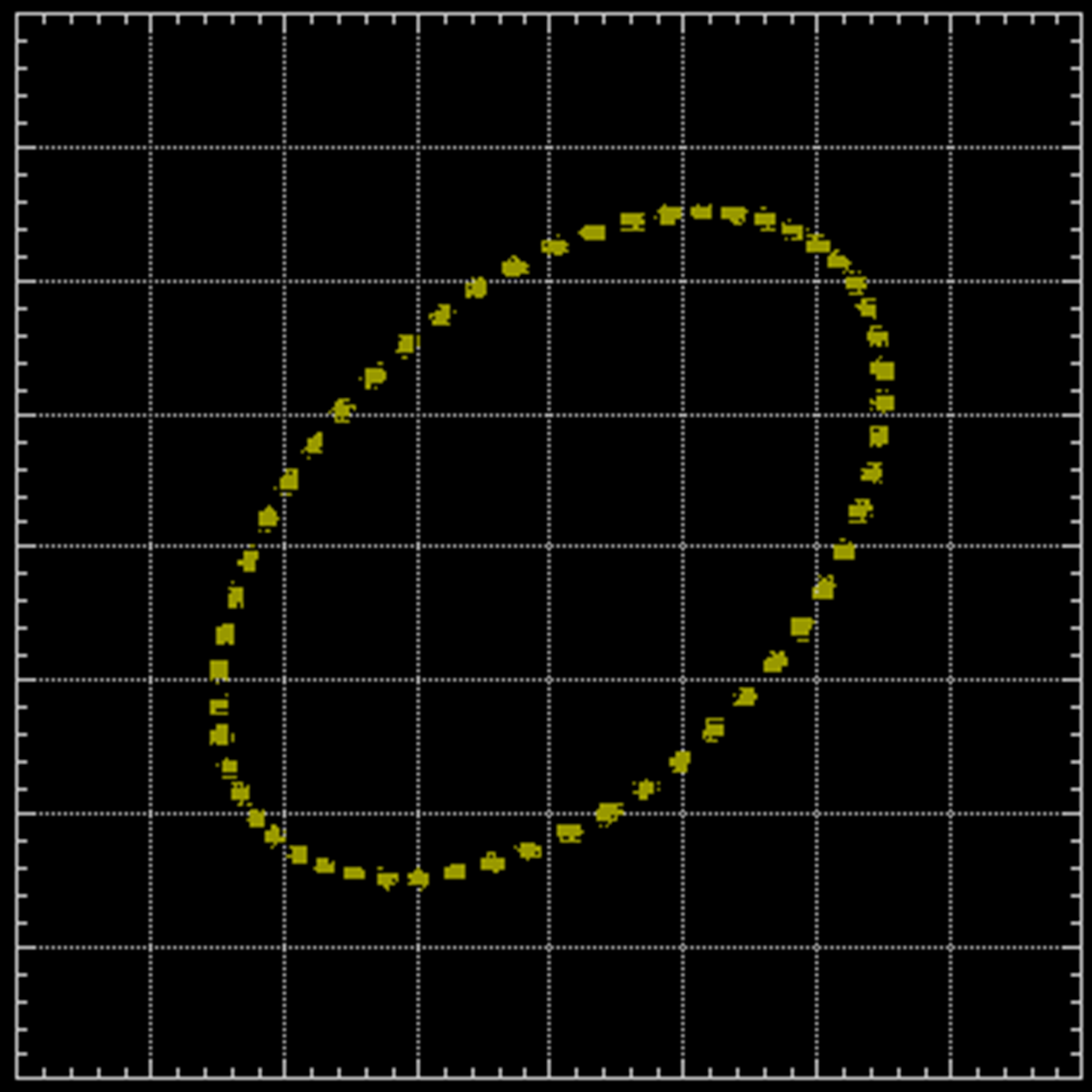
The XY oscilloscope representation of A and B is shown in the Fig. C. The left figure shows the analogue superposition. If the system is in rest, only a dot on the circumference of the ellipse (ideally a circle) indicates the position. A full turn is related to a traveled distance of λ/4 or 0.158 micrometer when λ is 635 nm and the rotation direction depends on the direction of movement.
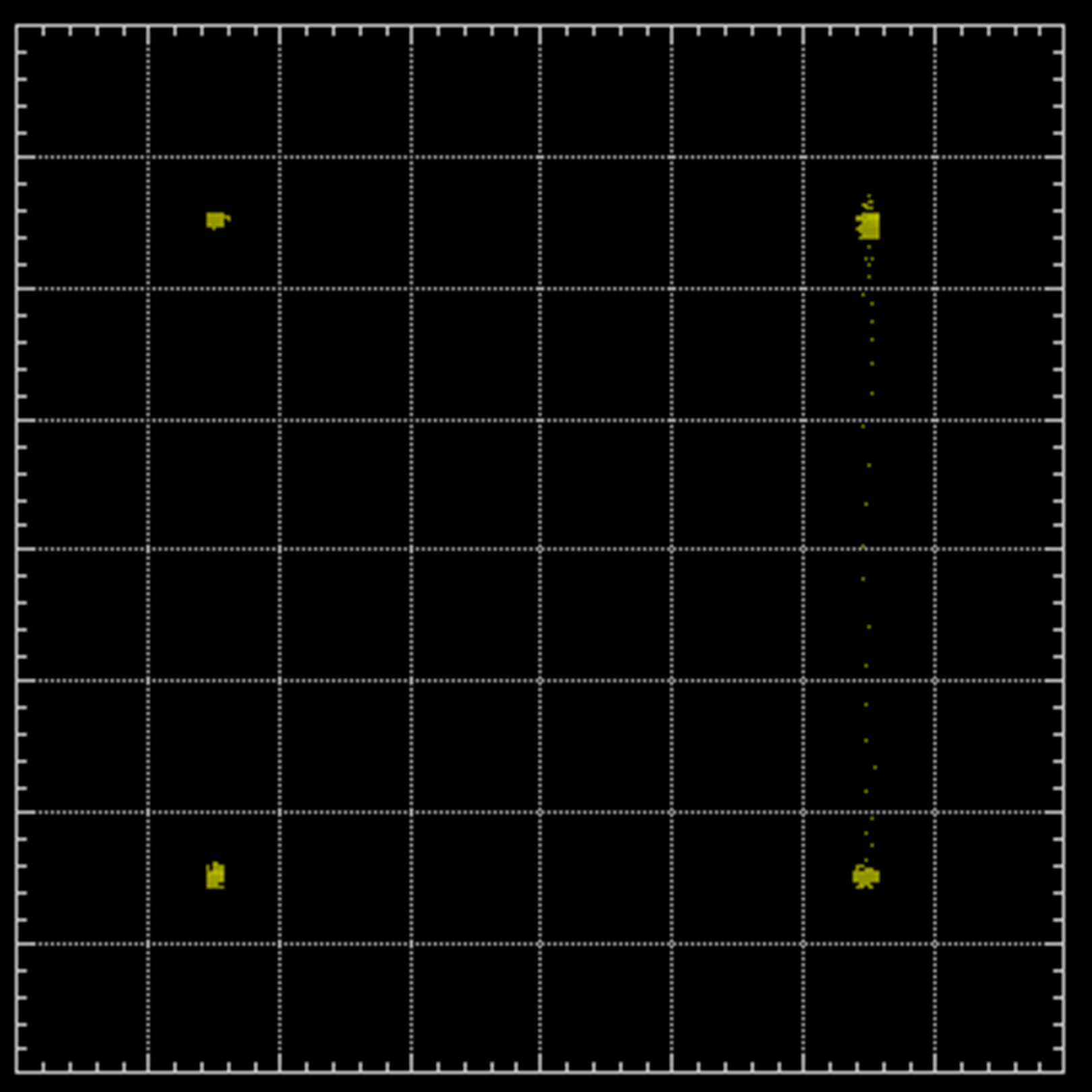
The right figure of Fig. C shows the XY representation of the TTL signals of C and D. Here, the dot jumps clockwise or counter-clockwise from one corner to the other whereby on jump corresponds to a movement of λ/16. The task of the electronics is to count how many jumps occur in clockwise and in counter-clockwise direction. This is achieved by using an up and down counter whereby the directional signal is gained from the 90° phase shift between both signals. If A leads B then the directional signal for the counter will be high (up) or low when B leads A.
The movement of the translation stage is controlled by the stepper motor controller. The increment as well as the speed is set to suitable values. After each increment the controller stops the movement for a while and the counted fringes are read from the counter display. Either the microprocessor or the student calculates from the counted fringes the traveled distance and creates a graph.
| Item | Code | Qty. | Description |
|---|---|---|---|
| 1 | DC-0100 | 1 | Stepper motor controller |
| 2 | ES-0200 | 1 | Interferometer control and logger software |
| 3 | MM-0140 | 1 | Triple reflector on motorized translation stage, travel 50 mm |
| Media Type | Title | File Size [MBytes] | Action |
|---|---|---|---|
| LM-0140 CNC Calibration Extension for LM-0100 Version 2010 |
6.93 MB | Download | |
| Catalogue Page | |||
| JPEG, PNG, SVG | Pictures | ||
| MP4 | Video |