Historic First Laser
Optical Pumping
Ruby Energy Level Diagram
CW Ruby Laser Emission
Lifetime of excited state
Spiking
Transversal Modes
Class 1 Laser
Beam Profiler
LE-1600 Ruby Laser RL4000
Topics:
A. LE-1600 Ruby Laser RL4000
The LE-1600 blue diode pumped Ruby laser is designed as a class 1 laser, albeit a class 4 diode laser (LD) is used generating class 3 laser radiation. By using protective shields and a micro processor controlled safety functions, under no circumstances laser light is accessible or leaves the system. For the different measurement tasks different sensors like an ordinary white screen, a photodiode or a CCD camera (CC) with slots for different filters (FB) can be attached to the system. Each module is equipped with an EEPROM carrying the information about what it is. The modules are plugged via three contact pins into one of the three slots (PL). All three slots are permanently scanned, providing the information what is plugged to which slot. Bases on this information the micro processor allows or prevents powering up the diode laser.
If a module is removed while the laser is powered up, the processor shuts the laser diode down within milliseconds.
The light of the laser diode (LD) is collimated and passes a focusing lens (FL) into the Ruby crystal (RC). Both lenses are integral part of the laser diode. The optical cavity is formed by the flat laser mirror M1 and the curved mirror M2. Both mirrors are mounted into adjustment holder allowing the adjustment of the cavity by the students.
The mirror M1 is a flat mirror with a high transmission for the pump light (405 nm) and a high reflectivity for the ruby laser wavelength of 694 nm. The mirror M2 has a radius of curvature of 50 mm and has a transmission of 1% for the ruby laser wavelength and a high reflectivity for the pump radiation.
The adjustment holder for the mirror M2 can be translated by turning the knob CL by 5 mm. The translation range corresponds to a cavity length from 47 mm to 52 mm.
The Figure A. shows the setup with the CCD camera module CC using a 12 MP chip as it is used in the Raspberry cameras. It is connected with a flat ribbon cable to the Raspberry PI attached to the standard 7 inch Monitor (MO). In front of the camera a filter box is plugged in where neutral density filters can be inserted to reduce the intensity of the Ruby laser light down to low levels suitable for the CCD chip. With this simple and economic beam profiler the different transversal modes can be displayed and documented. The camera is also a useful device for the initial alignment of the Ruby Laser. The fluorescence spots originating from the mirrors M1 and M2 are observed by the camera and displayed on the monitor (MO). By aligning the mirrors such that both spots are centered to each other, the Ruby laser starts lasing.
A. Principle of LE-1600 Ruby Laser RL4000
B. Ruby Laser RL4000 with attached lateral photodetector (PD)
C. Measuring the lifetime of the excited state
To measure only the fluorescence radiation without disturbing strong pump light, the photodetector (PD) is mounted perpendicular to the optical axis near the Ruby crystal. The photodetector is connected to the controller and operates in bias mode with software selectable shunt resistors and the output is connected to an oscilloscope. The injection current of the laser diode (VLD) is periodically switched on and off by the controller. The provided reference signal of the injection current is also connected to the oscilloscope and serves as trigger source on falling edge.
The corresponding oscilloscope track is shown in Fig. C. From the decay curve of the fluorescence signal the lifetime of the excited state is determined. The inverse value of it is related to Einstein coefficient for spontaneous emission.
D. Photodetector to measure the Ruby laser emission
E. Measuring the dynamic properties of the ruby laser
To measure the Ruby laser output a detector with a filter to block the violet pump radiation is used. The signal of the photodetector and the reference signal of the injection current is displayed on the oscilloscope. The example of the Figure E. shows the famous initial spiking when the Ruby laser starts to oscillate.
F. CCD camera to measure the intensity distribution of the Ruby laser emission

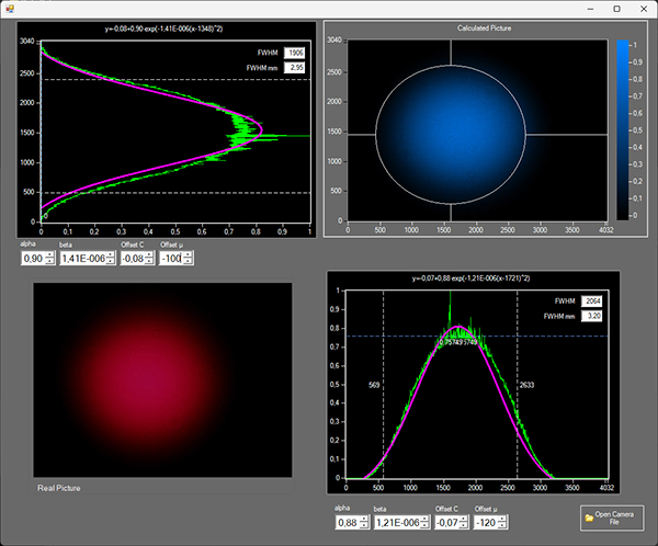
G. Display and measuring the intensity distribution of a TEM00 Ruby laser mode
The CCD image can be obtained from the Raspberry PI as real time image file (jpg) or as XY array data (csv). The image on the bottom left of Figure G. shows the jpg image and the upper right the xy array read and displayed by the provided windows software.

H. Measuring interference pattern of inserted objects
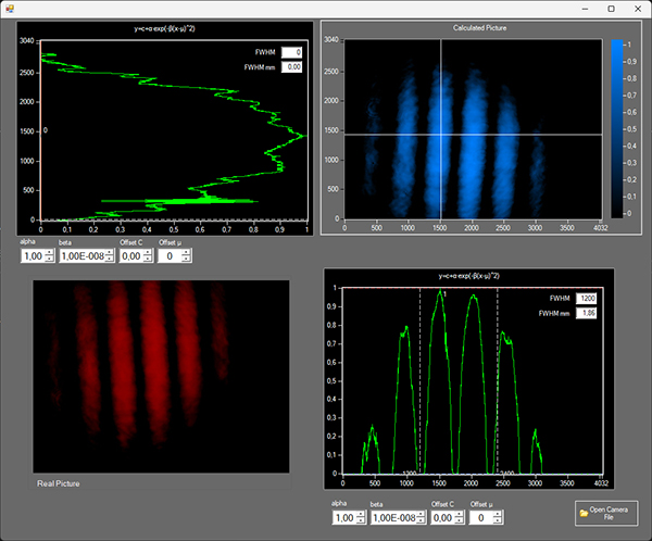
In addition to the neutral density filters other objects like slits or gratings can be inserted into the filter box causing characteristic interference pattern.
| Item | Code | Qty. | Description |
|---|---|---|---|
| 1 | LE-1610 | 1 | Ruby Laser RL4000 Basic |
| 2 | LE-1612 | 1 | Module Image screen |
| 3 | LE-1614 | 1 | Module Photodetector |
| 4 | LE-1616 | 1 | Photodetector |
| 5 | XT-0100 | 1 | Transport and storage box |
| 6 | XT-R010 | 1 | USB-C Power Delivery (USB-PD) 30W |
| Option (order separately) | |||
| 7 | LE-1620 | 1 | Module Filter Box |
| 8 | LE-1630 | 1 | Module CCD Camera |
| 9 | LE-1640 | 1 | Set of 3 absorptive neutral density filter |
| 10 | LE-1650 | 1 | Module Polarization |
| 11 | LE-1660 | 1 | Raspberry PI with 7 inch Display |
| Media Type | Title | File Size [MBytes] | Action |
|---|---|---|---|
LE-1600 Ruby Laser RL4000 |
12.7 | Download | |
LE-1600 Ruby Laser RL4000 |
12.7 | Download | |
| Catalogue Page | |||
| JPEG, PNG, SVG | Pictures | ||
| MP4 | Video Ruby Laser RL4000 (English) | 4,062 | Download |
| MP4 | Video Ruby Laser RL4000 (German) | 4,062 | Download |