Reflection Law
Fresnel Laws
Reflectance
Transmittance
Polarization
Anti-Reflection Coating
Brewster Angle
LED Characterization
Green Laser Properties
PE-0300 Reflection and Transmission
Topics:

PE-0300 Reflection and Transmission
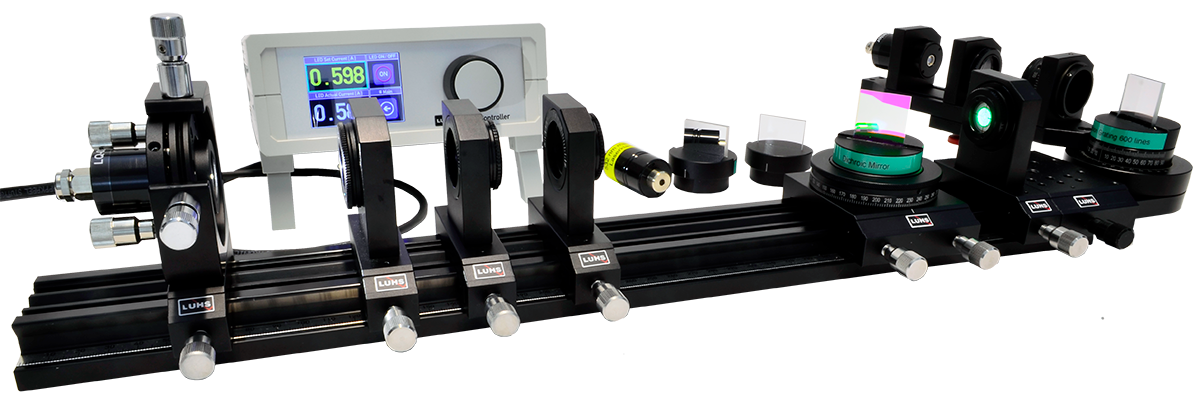
Reflection of light on surfaces is a familiar phenomenon of daily life. Therefore it is no surprise that the reflection law is one of the well known optical laws and was first stated by Ibn Al Haitham beginning of the 10th century. Little is commonly known about polarization of light and its connection with reflection and refraction. This connection is formulated in the Fresnel Laws which are usually expressed as transmittance and reflectance as a function of the index of refraction and angle of reflection. The four formulas which were deduced by Augustin Fresnel in 1821 contain the complete theory of reflection, refraction and polarization of isotropic materials. The fundamental understanding of reflection and transmission is essential for the design of laser mirror, sun glasses and a lot more. By dielectric coating such components are made either to optimize or to suppress reflection. Within this experiment the reflection law which is verified using a metal coated mirror. The next part covers the quantitative verification of the Fresnel Laws on a specially shaped glass plate using polarized light. Finally the spectral performance of a dielectric coated mirror is investigated using a white LED and a grating.
A. Measuring the Light Intensity and Polarization Property
B. Measure spatial intensity distribution
C. Measure Mirror properties
| Item | Code | Qty. | Description |
|---|---|---|---|
| 1 | DC-0020 | 1 | LED and Photodiode Controller |
| 2 | DC-0120 | 1 | Si-PIN Photodetector, BPX61 |
| 3 | LQ-0020 | 1 | Green (532 nm) DPSSL in ø25 housing |
| 4 | LQ-0200 | 1 | White LED in ø 25 Housing |
| 5 | MM-0020 | 1 | Mounting plate C25 on carrier MG20 |
| 6 | MM-0024 | 2 | Mounting plate C25-S on carrier MG20 |
| 7 | MM-0028 | 1 | Mounting plate C25-S with angle gradation |
| 8 | MM-0034 | 1 | Mounting plate C30 on carrier MG20 |
| 9 | MM-0300 | 1 | Carrier with 360° rotary arm |
| 10 | MM-0380 | 1 | MG65 carrier with rotary stage |
| 11 | MM-0420 | 1 | Four axes kinematic mount on carrier MG20 |
| 12 | MP-0150 | 1 | Optical Bench MG-65, 500 mm |
| 13 | OC-0060 | 1 | Biconvex lens f=60 mm in C25 mount |
| 14 | OC-0140 | 1 | Achromat f=40 mm in C30 mount |
| 15 | OC-0710 | 3 | Polarizer in C25 mount |
| 16 | OM-0310 | 1 | Dichroic mirror on rotary table |
| 17 | OM-0320 | 1 | Front face mirror on rotary table |
| 18 | OM-0330 | 1 | Glass plate on rotary table |
| 19 | OM-0340 | 1 | Transmission grating on rotary table |
| 20 | UM-PE03 | 1 | Manual Reflection & Transmission |
| Media Type | Title | File Size [MBytes] | Action |
|---|---|---|---|
| UM-PE03 Reflection and Transmission Version 2022 |
7.83 MB | Download | |
| Catalogue Page | |||
| JPEG, PNG, SVG | Pictures | ||
| MP4 | Video |