Eye safe short pulse laser diode
Peak Power
Laser Energy
Beam Collimator
Back scattered Light
Fast Si PIN Photodetector
Light Echoes
LIDAR - Light Detection and Ranging
Speed of Light
Range Finder
Pulse width control
LM-0400 Pulse Laser Range Finder
Topics:
 LM-0400 Laser Range Finder
The pulse duration must be modified to match the required resolution and distance. In this experiment the shortest pulse duration is 50 ns with a rise time of 5 ns. When the laser pulse is launched the receiver photo detector is also used to generate a start pulse signal which serves as trigger for the oscilloscope. The peak power of the laser diode amounts to 70 W within 100 ns which is related to an energy of 4µJ only. The intensity of the back scattered is very low compared to the laser pulse it self depending the scatter efficiency of the target. Furthermore the intensity drops with 1/r² where is the distance to the target. Consequently a photodetector with amplifier is applied. The controller allows also the characterization of the laser diode itself. The output power and pulse width as function of the parameters like charge voltage and discharge time can be measured and optimized for the length to be measured.
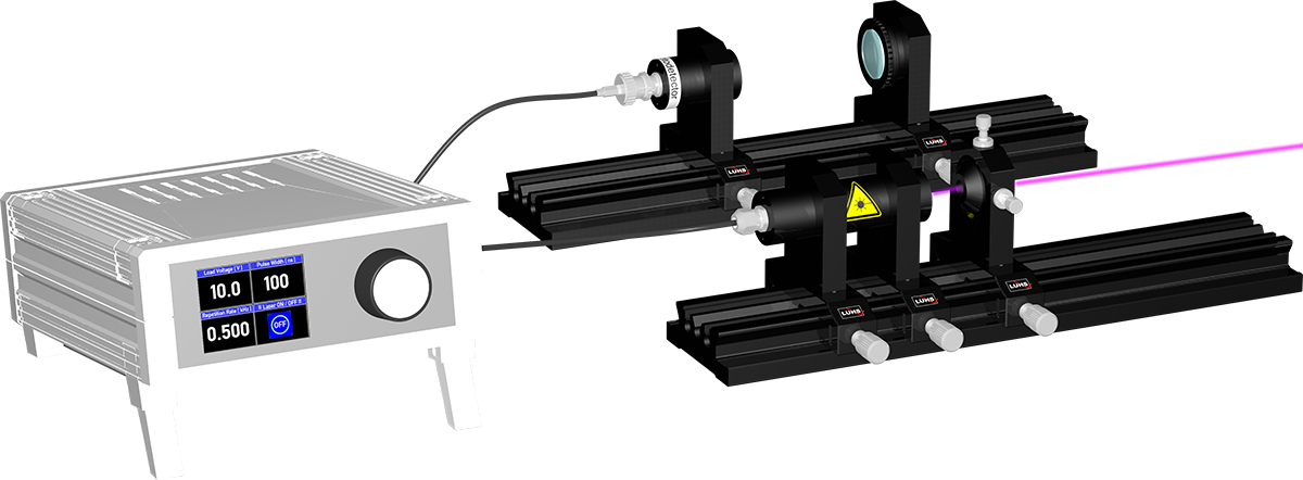
The emission of the pulsed diode laser is collimated to an almost parallel laser beam. At a certain distance it hits the target from which scattered light travels back depending on the scatter properties of the target. The receiver lens captures according to its field of view (FOV) a small fraction of it and focuses it onto a fast photodiode (Fig. A). Due to the fact that only a small fraction of the incident light comes back, a fast and sensitive amplifier is needed. For the operation of the laser range finder an oscilloscope is required. The Fig. B shows the principle of a measurement with target which is 10 m apart. The blue trace (E) shows the electrical pulse for the diode laser. To get the optical laser pulse at zero distance a target (sheet of A4 paper for instance) is held in front of the setup and the resulting curve is stored on the scope as reference curve (R). After removing the target at the zero position the new curve is stored as well. At the peak of the reference the time is defined as zero and the distance to the next peak gives the time of flight t for one round trip.
| Item | Code | Qty. | Description |
|---|---|---|---|
| 1 | CA-0060 | 1 | Infrared display card 0.8 -1.4 µm |
| 2 | CA-0450 | 2 | BNC connection cable 1 m |
| 3 | DC-0050 | 1 | Pulsed laser diode controller MK1 |
| 4 | DC-0220 | 1 | SiPIN Photodetector, ultrafast with amplifier |
| 5 | MP-0130 | 2 | Optical Bench MG-65, 300 mm |
| 6 | OM-0520 | 1 | Pulsed diode laser head in twofold rotary mount |
| 7 | OM-0620 | 1 | Collimating optics on carrier MG20 |
| 8 | OM-0622 | 1 | Focusing optics, f=60 mm on carrier MG20 |
| 9 | UM-LM04 | 1 | Manual Laser range finder |
| Required Option (order separately) | |||
| 10 | CA-0200 | 1 | Oscilloscope 100 MHz digital, two channel |
| Media Type | Title | File Size [MBytes] | Action |
|---|---|---|---|
| LM-0400 Laser Range Finder Version: under revision |
Download | ||
| Catalogue Page | |||
| JPEG, PNG, SVG | Pictures | ||
| MP4 | Video |