-
All visible radiation
-
Optical Pumping
-
Pr:YLF Energy Level Diagram
-
CW Pr:YLF Laser Emission
-
Lifetime of excited state
-
Spiking
-
Red, Green, Orange Laser Lines
-
Selective Resonator
-
Transversal Modes
-
Class 1 Laser
-
Beam Profiler
LE-1800 Pr:YLF Laser PL-4000
Topics:
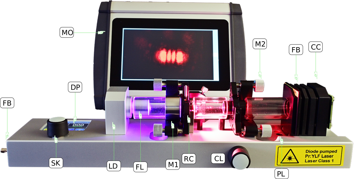 A. LE-1800 Pr:YLF Laser PL4000
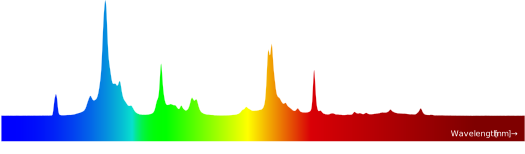 Pr:YLF Emission Spectrum. Laser lines at 523, 607 and 638 nm
A Pr:YLF laser (a praseodymium-doped yttrium-lithium fluoride solid-state laser) is particularly well suited for the direct generation of laser light in the visible spectral range (red, orange, green) as well as for UV applications. The Pr:YLF laser is likely the only solid-state laser that directly emits visible light. It is therefore ideally suited for practical training in the fields of laser technology and photonics. Laser safety plays a major role in training and often discourages some instructors from using lasers for teaching purposes.
For this reason, we have developed a Pr:YLF laser that meets the requirements of a Class 1 laser while still enabling investigations, measurements, and observations typically associated with a Class 4 laser.
Through the use of protective barriers combined with microprocessor-controlled safety features, laser light is prevented from being accessed or escaping the system under any circumstances. Various sensors, including a standard white screen, a photodiode, or a CCD camera (CC) fitted with slots for multiple filters (FB), can be connected to the system for specific measurement applications.
Within each module, there is an EEPROM that stores identity information. Modules are linked through three contact pins into one of the three slots (PL). All three slots are constantly checked to identify which module is present in each slot. Using this data, the microprocessor activates or deactivates the diode laser’s power supply.
Should a module be removed while the laser is running, the processor quickly shuts off the laser diode within milliseconds.
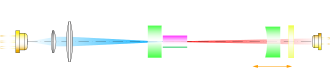
The light of the laser diode (LD) is collimated and passes a focusing lens (FL) into the Pr:YLF crystal (RC). Both lenses are integral part of the laser diode. The optical cavity is formed by the flat laser mirror M1 and the curved mirror M2. Both mirrors are mounted into adjustment holder allowing the adjustment of the cavity by the students.
The mirror M1 is a flat mirror with a high transmission for the pump light (405 nm) and a high reflectivity for the desired laser wavelength of 523, 607 oder 638 nm. The mirror M2 has a radius of curvature of 50 mm and has a transmission of 1% for the range of 500 - 700 nm and a high reflectivity for the pump radiation.
The adjustment holder for the mirror M2 can be translated by turning the knob CL by 5 mm. The translation range corresponds to a cavity length from 47 mm to 52 mm.
The Figure A. shows the setup with the CCD camera module CC using a 12 MP chip as it is used in the Raspberry cameras. It is connected with a flat ribbon cable to the Raspberry PI attached to the standard 7 inch Monitor (MO). In front of the camera a filter box is plugged in where neutral density filters can be inserted to reduce the intensity of the laser light down to low levels suitable for the CCD chip. With this simple and economic beam profiler the different transversal modes can be displayed and documented. The camera is also a useful device for the initial alignment of the laser. The fluorescence spots originating from the mirrors M1 and M2 are observed by the camera and displayed on the monitor (MO). By aligning the mirrors such that both spots are centered to each other, the laser starts lasing.
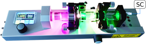

 A. Principle of LE-1800 Pr:YLF Laser PL4000
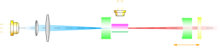 B. Pr:YLF Laser PL4000 with attached lateral photodetector (PD)
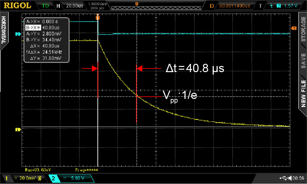
C. Measuring the lifetime of the excited state
To measure only the fluorescence radiation without disturbing strong pump light, the photodetector (PD) is mounted perpendicular to the optical axis near the Ruby crystal. The photodetector is connected to the controller and operates in bias mode with software selectable shunt resistors and the output is connected to an oscilloscope. The injection current of the laser diode (VLD) is periodically switched on and off by the controller. The provided reference signal of the injection current is also connected to the oscilloscope and serves as trigger source on falling edge.
The corresponding oscilloscope track is shown in Fig. C. From the decay curve of the fluorescence signal the lifetime of the excited state is determined. The inverse value of it is related to Einstein coefficient for spontaneous emission.
 D. Photodetector to measure the the dynamic properties of the Pr:YLF laser
To measure the Ruby laser output a detector with a filter to block the violet pump radiation is used. The signal of the photodetector and the reference signal of the injection current is displayed on the oscilloscope.
E. Selection of Laser Lines with Mirrors
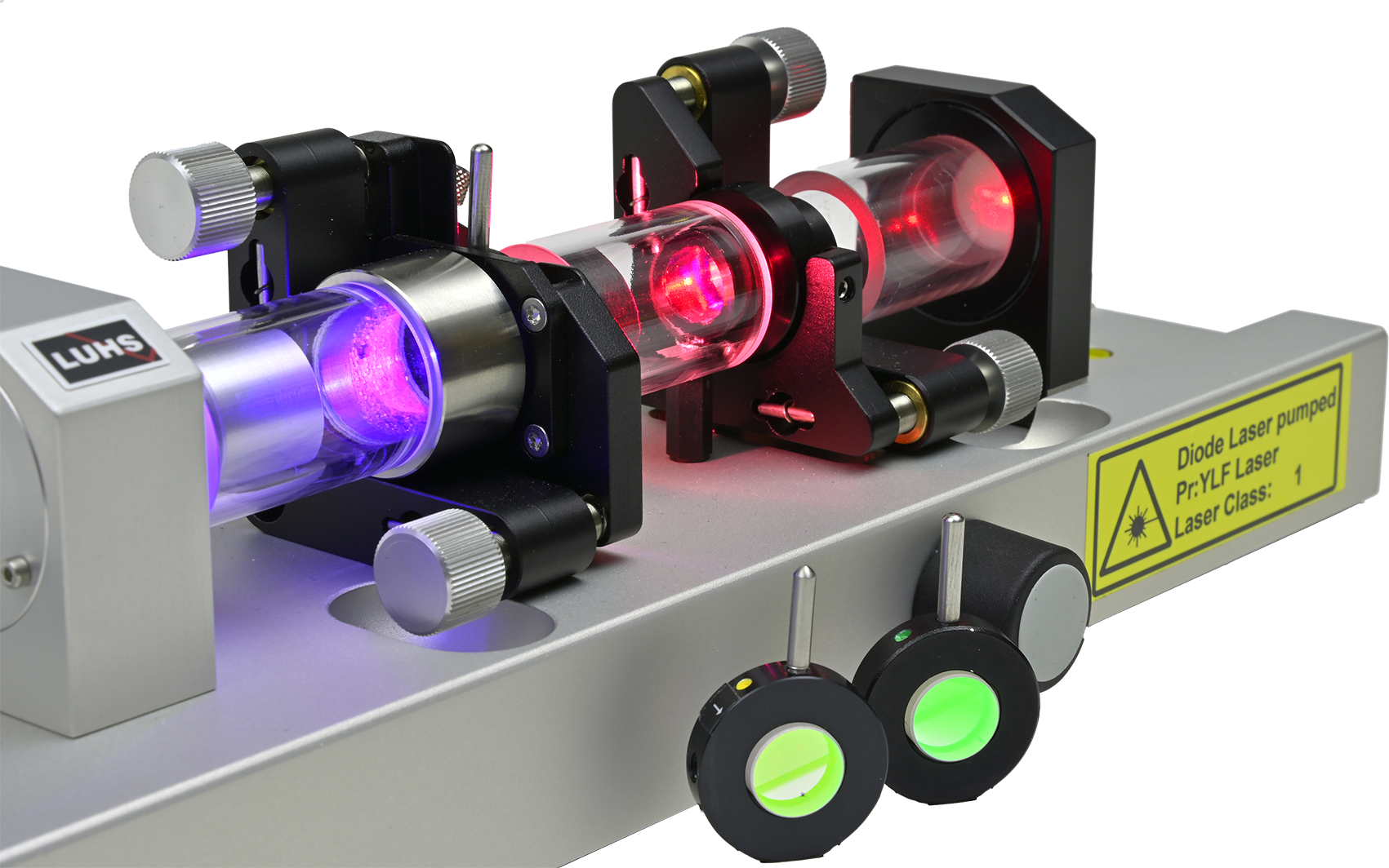 The curved mirror M2 is highly reflective (99%) in the 500–700 nm range. To select the wavelengths of 523, 607, and 638, we use three differently coated mirrors. The reflectivity of each mirror is >99% only for the desired wavelength and < 50% for the undesired wavelengths. In a hemispherical laser resonator, the alignment of the plane mirror is not as critical. Therefore, we swap it out for the desired wavelength. The mirror holders are held in a defined position by magnets, so that the resonator remains aligned even after a mirror change. The mount for the laser mirror holder features a magnetic sensor that is monitored by the microprocessor. If no mirror is inserted, the processor turns off the pump laser diode; as soon as a mirror is detected, the pump laser diode can be turned back on.
F. Rayleigh Scattering
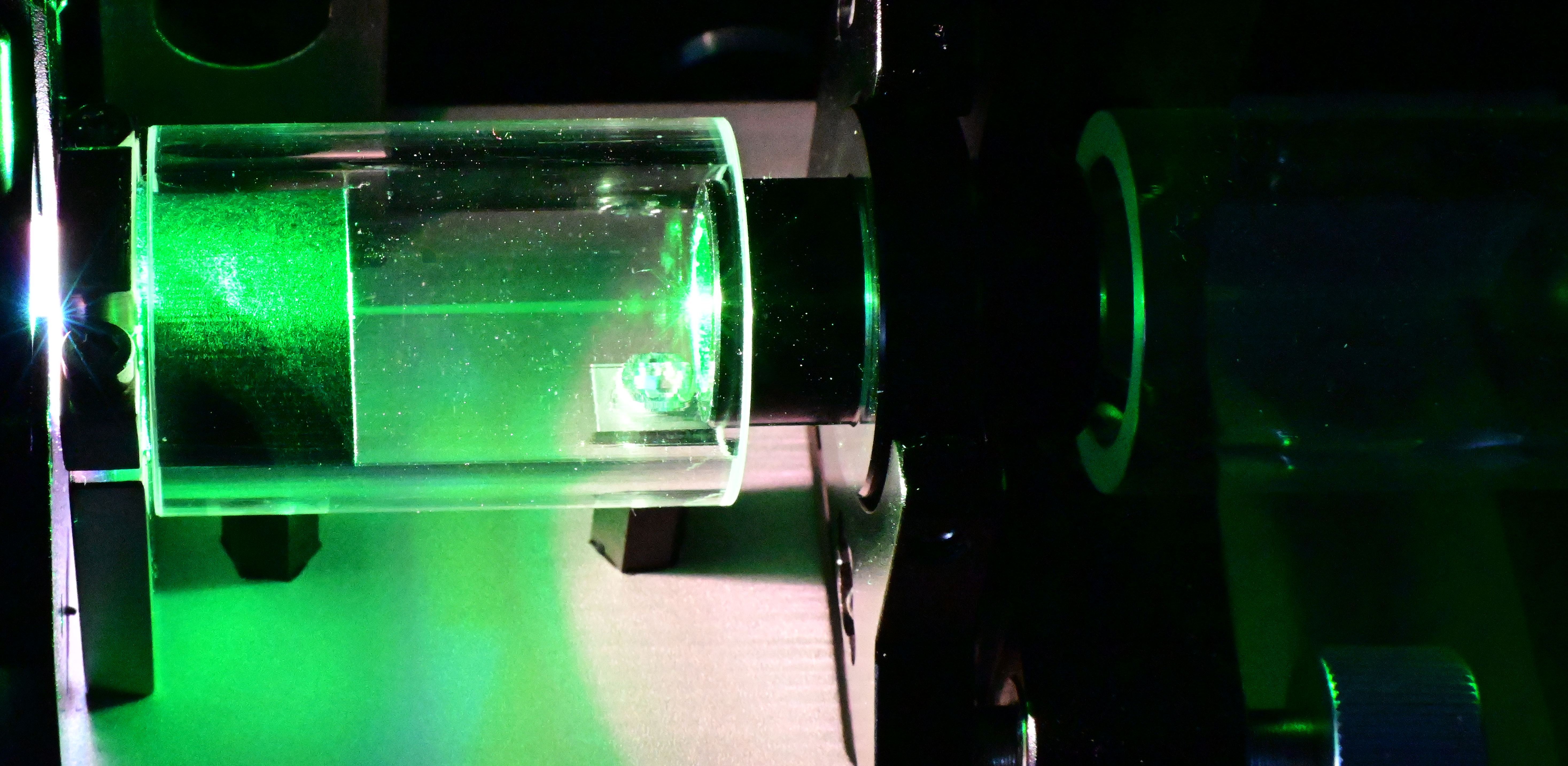 View into the cavity. Operating the green (523 nm) line
Because the output power from mirror M2 is low, the laser radiation inside the resonator has a high intensity. This leads to a unique phenomenon known as Rayleigh scattering. The dipoles of the air molecules are aligned by the high field strength and emit scattered radiation perpendicular to it. The polarization of the scattered radiation can be visually detected using a polarization analyzer.
G. CCD camera to measure the laser intensity distribution
 The filter and camera modules are inserted into their respective slots. The camera's CCD chip is illuminated directly by the laser beam. Gray filters (ND) with optical densities of OD2, OD3, and OD4 are inserted into the filter module; these reduce the intensity enough to prevent the camera from being overdriven. The camera is connected to a Raspberry Pi with a 7-inch screen.
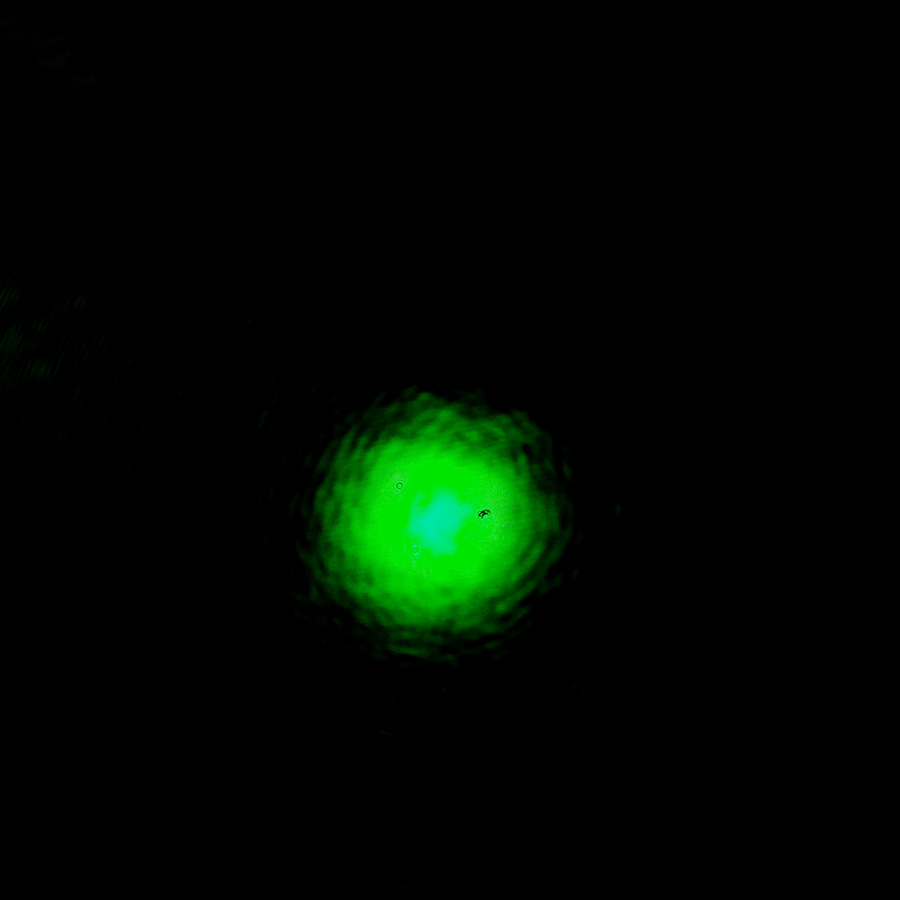 Green TEM0 0
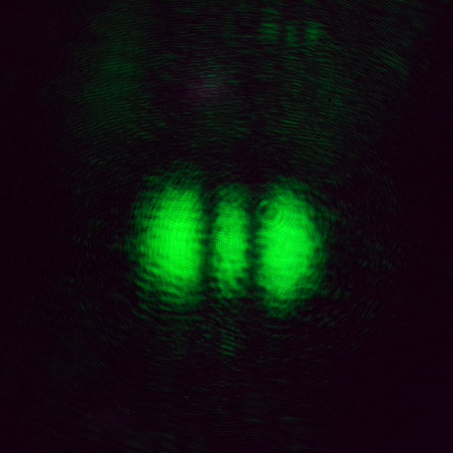 Green TEM2 0
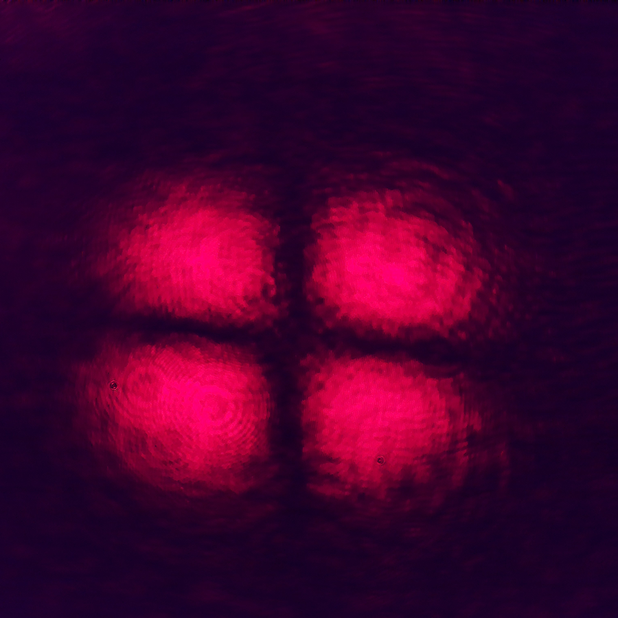 Red TEM1 1
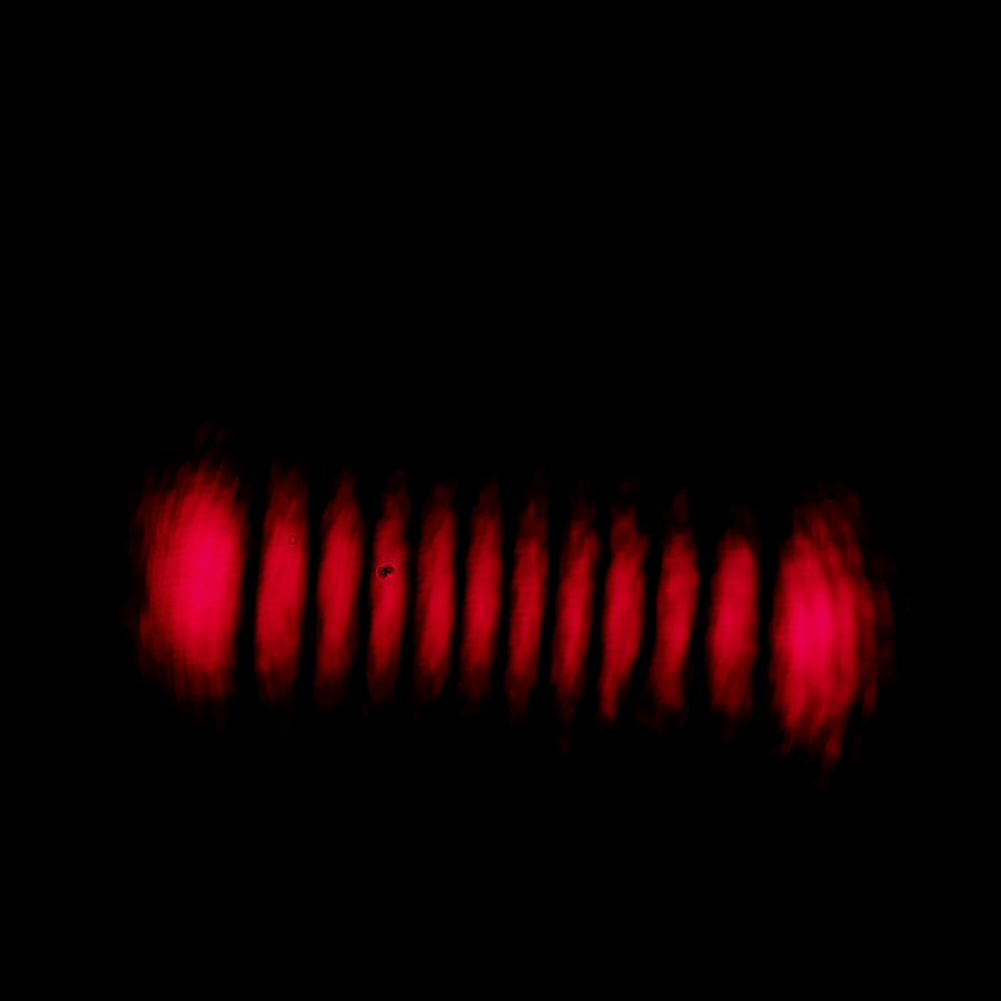 Red TEM11 0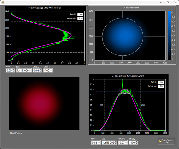
The CCD image can be obtained from the Raspberry PI as real time image file (jpg) or as XY array data (csv.